The joint is usually the first part of a conveyor belt to fail and the last part maintenance teams plan for. No single splice suits every belt. The right choice depends on the carcass, the tensile load, the duty, and the site conditions.
Key Takeaways
- Every joint becomes the weakest section of the belt.
- Rubber and PVC/PU belts use completely different joining processes.
- Joint strength depends as much on workmanship as on hardware.
- Choose in this order: carcass, belt strength, duty, site.
- Vulcanized splices suit high tension; fasteners suit quick access.
- Cold bonding suits repairs and low-tension fabric belts, not steel cord.
1. First, Know Which Belt You Are Joining
Two questions decide almost everything about a conveyor belt joint: what the belt is made of, and what carries the tension. Belt construction, cover grade, and rated tension set the design limits of the splice, and they explain why conveyor belt types cannot share one joint method.
Figure 1 – Labeled cross-section of a rubber belt showing cover, fabric ply or steel cord carcass, and the joint area. Image to be supplied by the manufacturer.
1.1 Rubber Belting vs. PVC/PU Belting
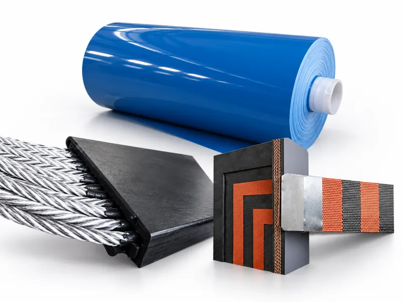
Rubber belts are thermoset: their covers and plies are bonded by vulcanization, so a joint is made by curing rubber in place or by clamping the belt mechanically. PVC and PU belts are thermoplastic, so they are joined by softening the material with heat and pressing the ends together. The two processes are not interchangeable.
1.2 Fabric Carcass vs. Steel Cord Carcass
Fabric belts use woven plies, usually EP or NN, which carry the tension, so a stepped or finger splice must rebuild those plies layer by layer. Steel cord belts use parallel cords embedded in rubber, and every cord must be reconnected with the correct overlap and spacing. That is why steel cord splices are multi-stage and far less forgiving. Heat-resistant, fire-resistant, oil-resistant, chevron, and sidewall belts are variants of these groups.
Belt construction | What carries the tension | How it is normally joined |
Rubber, fabric carcass (EP, NN, cotton) | Woven fabric plies | Stepped or finger vulcanized splice; mechanical fastener at low tension |
Rubber, steel cord carcass | Parallel steel cords | Multi-stage vulcanized splice |
PVC or PU, light fabric or monolithic | Fabric or homogeneous thermoplastic | Finger splice with welded seam; clips on very light belts |
2. What Is a Conveyor Belt Joint?
A conveyor belt joint is the finished connection between two belt ends. The term describes the completed connection, not the hardware that produces it. Confusing the two is a common error in specification writing.
2.1 Joint vs. Splice vs. Fastener vs. Clip
- Joint: the finished connection between belt ends.
- Splice: the same thing, and the usual word for a vulcanized connection.
- Fastener: metal hardware such as a plate, hinge, tooth, or hook.
- Clip: a small fastener, typically used on light belts.
- Belt joint clamp: a tool that holds the belt ends. Equipment, not a joint.
- Belt joint machine: a vulcanizing press or welding unit. Equipment, not a joint.
Fasteners and clips are hardware within one type of conveyor belt joint. Clamps and presses are the tools used to install them, which is why the type of conveyor belt splices and the types of conveyor belt joints form the same list.
2.2 What Every Joint Has to Do
Every joint has three jobs. It must transmit belt tension without overloading the transition, keep the belt flat, aligned, and close to its original thickness, and seal the carcass against water, fines, and chemicals. Failing any one of these causes an early failure.
3. The Three Families of Conveyor Belt Joints
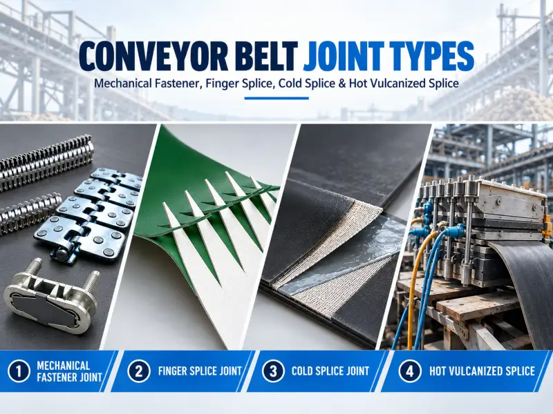
Every practical conveyor belt joint type belongs to one of three families: mechanical, cold bonded, and hot vulcanized. They differ in how they transfer tension, what equipment they need, and how much strength they retain.
3.1 Mechanical Splices
Hardware is driven into or clamped onto the belt ends, so the joint can be installed with hand tools and removed again. It is fast and useful, but it punctures the carcass and retains less strength.
3.2 Cold Bonded (Cold Vulcanized) Splices
The splice is built in layers and bonded with cement that cures at ambient temperature, with no press. It is sensitive to preparation, temperature, and moisture, and it suits fabric belts and repairs.
3.3 Hot Vulcanized Splices
Uncured rubber is placed in the joint and cured under heat and pressure, so the splice becomes a continuous rubber body with the belt. It restores the most strength, and it needs a press, power, and a trained crew.
Attribute | Mechanical | Cold bonded | Hot vulcanized |
How it connects | Hardware clamped or driven through the belt ends | Layered splice bonded with cement, cured at ambient temperature | Rubber compounds cured under heat and pressure |
Belt types | Fabric; light PVC/PU | Fabric, and repair patches | Fabric and steel cord |
Relative strength | Low to medium | Medium | High |
Equipment and skill | Hand or powered applicator | No press; depends on preparation and climate | Press, power, trained crew, controlled conditions |
On-site | Yes | Yes | Yes, with equipment |
Removable | Yes | No | No |
Typical use | Fast repairs, low to medium tension, temporary joints | Repairs, low to medium tension fabric belts, sites without a press | Mainline belts, high tension, steel cord, long service life |
Relative strength is a qualitative ranking. Any figure for retained belt strength, and any joint acceptance criterion, must come from the belt manufacturer’s splice specification and the applicable standard. Do not use a general percentage as a design value.
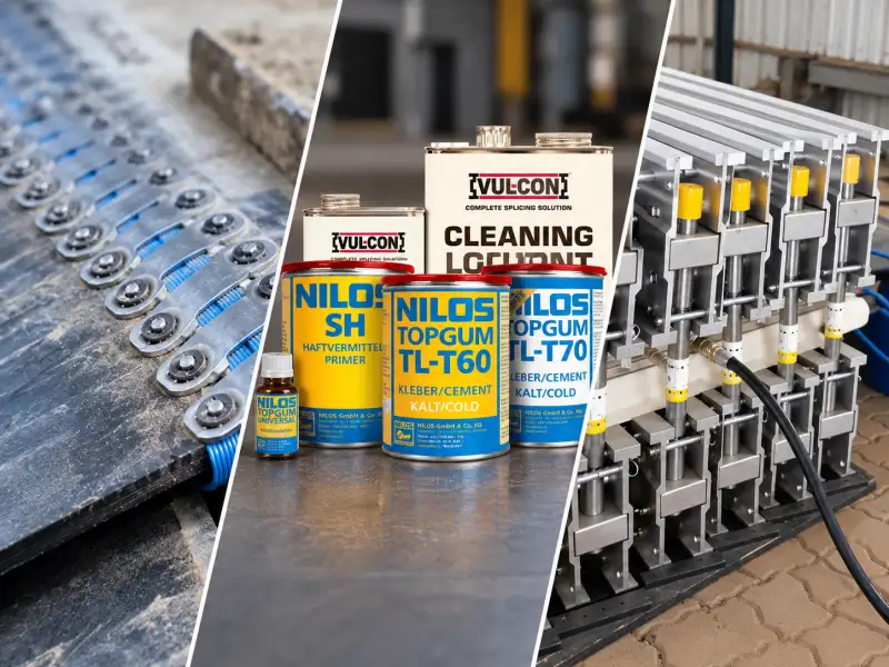
4. Mechanical Belt Joints: Plate, Butterfly, Toothed and Sleeve-Type Fasteners
Mechanical conveyor belt joints connect two belt ends using metal fasteners or reinforced connecting sleeves. Most can be installed with hand tools or powered applicators, allowing the belt to return to service without vulcanization. Their main limitations are localized carcass stress, possible changes in joint thickness, and splice strength that depends on the fastening system.4.1 How Mechanical Fasteners Hold the Belt
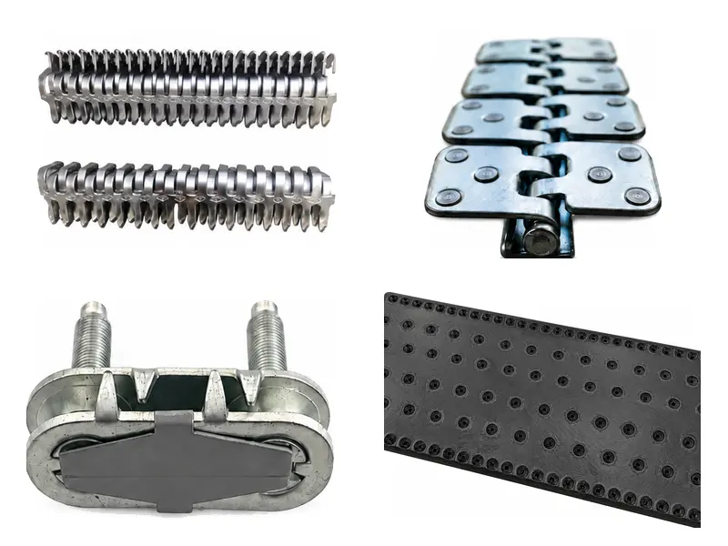
Traditional fasteners use teeth, rivets, bolts, or hooks to secure the belt ends. Plates compress the belt, while hinged designs use a connecting pin to allow bending around pulleys. Reinforced joint sleeves use screws and flexible connecting sections to transfer tension across the splice.
Each system distributes load differently. Fastener penetration, clamping pressure, belt construction, and joint flexibility determine how well the connection withstands operating tension and repeated bending.
4.2 Solid Plate and Bolt Fasteners
A solid plate fastener clamps both faces, with bolts or rivets through the ends. It suits thicker belts and higher mechanical tension, and its bolts can be re-tightened. It leaves a full row of holes across the belt, which reduces the section available to carry load.
4.3 Butterfly and Hinged Fasteners
A butterfly or hinged fastener uses two fastening sections joined by a hinge pin. Each section is fitted to one belt end, and the pin is inserted afterwards. The ends can be separated for maintenance or for adding a belt section. The pin is also a wear point where fines can accumulate.
4.4 Toothed (Alligator-Type) Fasteners
Toothed fasteners drive pointed teeth through the belt and clinch them against the underside. They are quick, compact, and common on light- to medium-duty fabric belts. Because the teeth penetrate fabric yarns, the joint can be vulnerable to tear-out under excessive tension or shock loading.
4.5 Belt Joint Sleeves (Flexible Mechanical Splices)
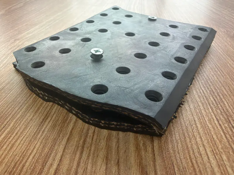
Belt joint sleeves use reinforced rubber or composite connecting sections secured to the prepared belt ends with screws or bolts. Some designs have interlocking sections that help align the splice. They provide a flexible, relatively low-profile connection without hot vulcanization or adhesive curing.
These sleeves are useful where access is limited or downtime must be minimized. Unlike rigid metal plates, flexible designs can accommodate repeated pulley bending, provided the selected model meets the required pulley diameter and working tension. Their suitability depends on belt thickness, carcass construction, fastener retention, and the manufacturer’s splice rating.
4.6 Staples, Rivets, Wire Hooks and Clips
Wire hooks, staples, rivets, and small conveyor belt joint clips complete the mechanical family. Wire hooks provide a low-profile connection for lighter-duty applications, while staple and rivet fasteners cover different belt thicknesses and tension ranges. These systems are also used on lightweight PVC and PU conveyor belts where mechanical joining is preferred over thermal welding.
4.7 When a Mechanical Joint Is the Wrong Choice
Mechanical joints are not automatically suitable for steel cord belts, high-tension mainlines, or conveyors requiring maximum splice reliability. Even reinforced sleeve systems must be checked against the manufacturer’s working-tension rating and minimum pulley diameter. Damaged belt ends should be trimmed back to sound material before installation. Common failure mechanisms include fastener pull-out, carcass tearing, joint fatigue, and progressive loosening.
Attribute | Solid plate and bolt | Butterfly and hinged | Toothed (Alligator type) | Belt joint sleeves | Wire hooks and lacing | Staples and rivets |
Typical belt thickness | Thick | Medium | Thin to medium | Model-dependent | Thin | Thin to medium |
Load level | Medium to high | Medium | Low to medium | Medium to high, depending on model | Low | Low to medium |
Installation speed | Slow | Medium | Fast | Fast | Fast | Fast |
Carcass damage | Through-holes | Localized penetration | Teeth penetrate yarns | Screw penetration; model-dependent | Localized penetration | Localized penetration |
Notes | Re-tightenable; needs access to both faces | Detachable; hinge pin requires inspection | Compact; sensitive to excessive tension | Flexible; no vulcanizer; check pulley diameter and splice rating | Low profile; light-duty applications | Available in different fastening designs |
5. Hot Vulcanized Joints: Steps, Carcass Types and Equipment
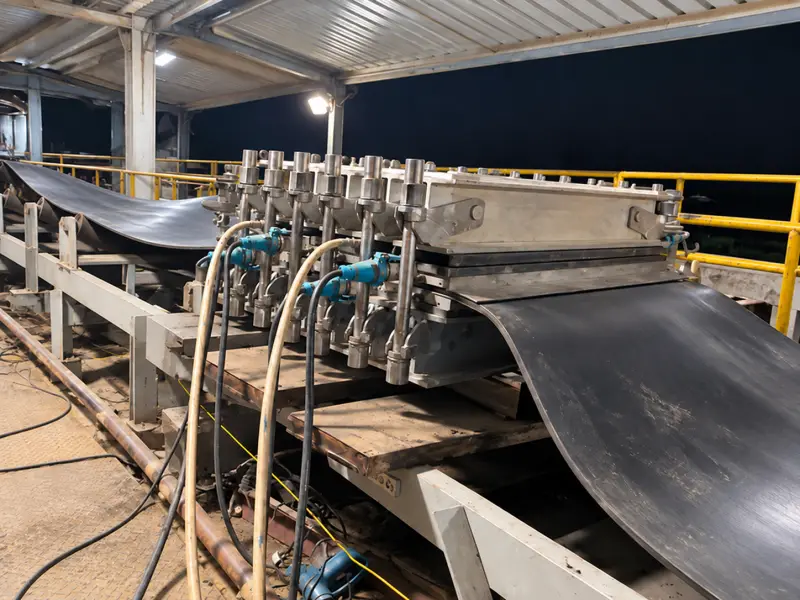
Hot vulcanization is the only method that returns most of a belt’s original strength. The ends are prepared to a defined geometry, rebuilt with uncured rubber, and cured under heat and pressure until the splice becomes one continuous body with the belt.
Figure 2 – Portable vulcanizing press set up on a belt line, with belt joint clamps holding both ends. Image to be supplied by the manufacturer.
5.1 How Hot Vulcanization Bonds the Carcass
Rubber cures by crosslinking. Uncured tie gum goes between the rebuilt plies, and cover compound restores both surfaces. Under heat and pressure the compounds fill voids and cure into a bond with the original rubber. No holes are made in the carcass.
5.2 Stepped Splices for Fabric Belts
In a stepped splice each ply is exposed in turn, so the ends interlock like a staircase. Step count follows the ply construction, and step length grows with rated strength. Higher-strength fabric belts often use an interlocking finger splice instead, because it spreads the load over a longer transition. Step length, finger length, and cover bevel come from the manufacturer’s splice specification.
5.3 Multi-Step Splices for Steel Cord Belts
Steel cord belts use a multi-stage splice: the cords from one end are laid into the other in a staggered arrangement, keeping spacing and overlap within tolerance. Spacing must not change, cords must stay in one plane, and any gap or contamination is a permanent defect. There is no mechanical alternative for a production splice.
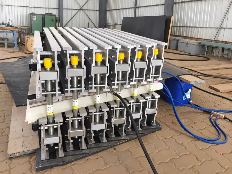
5.4 Portable Vulcanizing Presses and Belt Clamps
A belt joint machine is usually a portable vulcanizing press: heated platens, a cooling circuit, pressure, and a control panel. The platen must cover the splice plus a margin on every side, as the press manufacturer specifies. Belt joint clamps hold, pull, and align the ends while the joint is stripped and the press closes, and they keep belt tension off the joint.
5.5 Why Temperature, Pressure and Time Matter
Cure temperature is set by the compound. Published schedules for common rubber covers are often in the region of 140 C to 150 C, but your value is the one in the belt or compound supplier’s cure chart; pressure and time follow the same rule. The joint must also be cooled under pressure before the press is opened.
Parameter out of control | What goes wrong in the joint |
Temperature too low, or time too short | Under-cured splice; low bond strength, soft rubber, early opening |
Temperature too high, or time too long | Over-cured, hardened, cracked cover; possible reversion |
Pressure too low | Voids, blisters, incomplete contact between layers |
Pressure too high | Compound squeezed out, thinned section, distorted edges |
Moisture, oil, or dust in the joint | Blisters, weak bond, delamination along a step edge |
Uneven platen heat or an untrue press | Uneven cure, a thickness step, and a weak side |
6. Cold Bonded Joints and Bonding Materials
Cold bonding is a rubber conveyor belt jointing solution that uses cement systems instead of a press. The splice is built in layers and cured at ambient temperature, which makes it the practical choice for repair work and for sites where a press cannot be brought to the belt.
6.1 How Cold Bonding Works
A cold bonding system is an adhesive system. A cement, often supplied as a base and a hardener, wets both prepared surfaces and cures over several hours. Clean, dry, correctly roughened surfaces matter far more than they do in a hot splice, because the cement itself has to form the bond.
6.2 Materials: Cements, Tie Gum and Cover Compounds
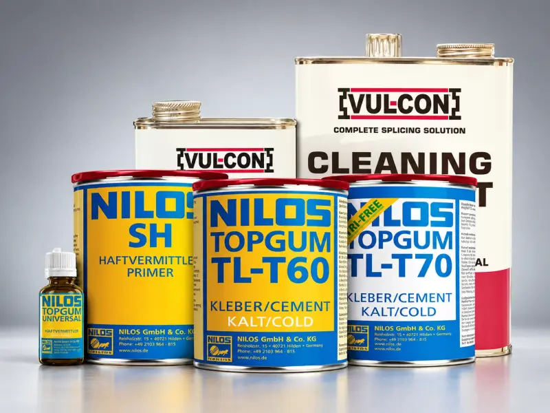
Jointing compounds fall into two families and are not interchangeable. Hot-vulcanizing compounds, including tie gum and cover compound, are cured in a press; cold-curing cements harden at ambient temperature.
- Cement: the adhesive layer; two-component versions need an accurate mix ratio and pot life.
- Tie gum or cushion gum: uncured rubber sheet that rebuilds ply layers and splice thickness.
- Cover compound: restores the cover, as a cold-cure compound or a hot-vulcanized strip.
6.3 Preparation and Surface Requirements
The fabric must be completely dry, and rubber surfaces are buffed to a matte finish, cleaned, and dried. Cement is applied in thin, even coats with the supplier’s open time, and each layer is rolled from the center outward to remove trapped air. The joint is then clamped for the full cure time. Many systems also require an ambient and surface temperature of at least about 15 C, and a dry environment.
Condition during work | Effect on the joint |
Temperature below the supplier minimum | Slow or incomplete cure; the joint may never reach full strength |
High humidity, or a wet belt surface | Blisters and a weak bond at the interface |
Oil, dust, rust, or release agent | Local disbond and lifting at the step edge |
Open time too short or too long | Poor wetting, or an adhesive surface that has already dried |
Insufficient rolling or clamping pressure | Trapped air and voids inside the splice |
6.4 Limits of Cold Bonded Joints
Cold bonding is not used for steel cord belts, and it does not match a correctly made hot splice on the same fabric belt. Treat it as a repair and light-duty method: low and medium tension fabric belts, patches, and field fixes where production cannot wait for a press. Adding extra hardener does not make the joint cure faster; it usually makes it brittle.
7. Rubber Conveyor Belt Jointing Solution by Application
The belt construction sets the method; the duty sets the details. The same EP belt can need a different conveyor belt joint solution depending on its cover grade, its environment, and the material it carries. One rule runs through the whole section: the joint compound is normally a conventional splice compound chosen for adhesion, not a compound of the same special grade as the belt cover. Special-property compounds generally have lower tack, so a joint built with them can bond poorly even when the grade matches on paper. This section covers the choices that most often go wrong.
7.1 Heat-Resistant Belts
Use the conventional splice compound recommended for the belt, not a compound matched to the heat-resistant cover grade. Heat-resistant covers are specified and tested under standards such as GB/T 33510, but that grade is chosen for the carrying surface, not for the bond. Compounds with special properties generally develop lower tack and adhesion, so matching the cover grade at the joint can leave the bond weak and cause premature aging and delamination at the step edges. A hot duty does not make the joint less critical: a thicker joint still takes longer to cure, local overheating still cracks the cover, and cold bonding remains a temporary measure.
7.2 Fire-Resistant and Anti-Static Belts
Fire-resistant belts are specified under standards such as GB/T 10822 and HG/T 3973, and the splice must not break the properties the belt was bought for. An anti-static belt works because its surface resistance is controlled, so the conductive path has to continue across the joint; confirm with the supplier that the recommended joint compound preserves it. The same question applies to flame retardancy. Ask which joint compound is recommended for that belt, and do not assume that a compound carrying the same special property as the cover will produce a better joint. Exposed metal fasteners may also be restricted by local rules, and a vulcanized splice is then the normal choice.
7.3 Oil and Acid Resistant Belts
Choose the joint compound on the adhesion it develops on that cover, then check that it tolerates the chemical actually present. Oil-resistant covers are usually nitrile-based and can be difficult to bond, so ask the belt or splice-material supplier which compound they recommend for that grade rather than assuming that a compound with the same oil resistance will bond better. Protect the joint from the chemical during the cure, and choose fastener materials that will not corrode in the same environment.
7.4 Chevron, Sidewall and Rough-Top Belts
On chevron and rough-top belts, the profile is interrupted at the joint and the joint area is normally made flat; that strip changes the material path locally, so on steep inclines the load can slip at the joint, and skirt board clearance must be checked there. On sidewall belts, the base belt is spliced first, then the sidewall, with the sidewall seam offset from the base splice. Guide profiles are cut back and re-welded at the original position and height.
Figure 3 – Joint area of a chevron belt and a sidewall belt, showing the flat joint strip and the offset sidewall seam. Image to be supplied by the manufacturer.
Duty | Mechanical | Cold bonded | Hot vulcanized | Why |
General fabric belt, low tension | Suitable | Suitable | Suitable | Choose on access and downtime |
General fabric belt, high tension | Limited | Limited | Suitable | Cured splice retains the most strength |
Steel cord, high tension | Not recommended | Not recommended | Suitable | Cords must be reconnected in a controlled pattern |
Heat-resistant | Limited | Temporary only | Suitable | Conventional splice compound; bond strength comes first |
Fire-resistant and anti-static | Conditional | Conditional | Suitable | Splice must preserve flame and anti-static properties |
Oil or acid resistant | Conditional | Conditional | Suitable | Compound and hardware must resist the chemical |
Chevron, sidewall, rough-top | Limited | Limited | Suitable | Profiles must be rebuilt or offset at the joint |
Light PVC/PU belt | Suitable | Not applicable | Not applicable | These belts are joined by welding |
Emergency repair | Suitable | Suitable | Depends on equipment | Restore production first, then plan the permanent joint |
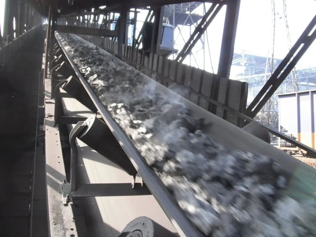
8. PVC and PU Conveyor Belt Joints: A Different Process Entirely
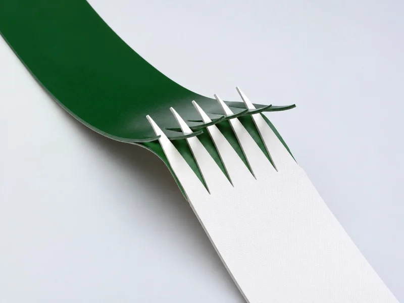
PVC and PU belts are joined by welding, not by vulcanization. The two ends are cut into an interlocking finger pattern, heated until the material softens, and pressed together so the fingers fuse into a continuous belt. A rubber belt jointing solution therefore cannot simply be transferred to a thermoplastic belt.
Figure 4 – Finger pattern marked on a PVC belt end, and the finished welded seam. Image to be supplied by the manufacturer.
8.1 Finger Splices and Hot Air Welding
The finger geometry depends on belt thickness and tension. Fingers must interlock without overlapping, and the weld must reach the full belt thickness. Hot air welding uses a blower with a shaped nozzle and a pressure roller. PVC belts are also joined with heated presses and, for suitable constructions, high-frequency welding; PU belts are normally hot air welded with a compatible weld rod or filler.
8.2 Overlap vs. Butt Welding
An overlap weld places one end over the other and fuses them. It is simpler and is still used on light belts and for temporary repairs, but it leaves a thickness step that can catch on a scraper or a tight pulley. A butt weld joins the prepared ends edge to edge with interlocking fingers and filler and keeps the thickness uniform, so it is normally the better choice for food handling and for belts with scrapers.
8.3 Where Mechanical Clips Still Make Sense
Very light PVC and PU belts, short runs, and temporary repairs can still be joined with small mechanical clips or lacing. They install without a welding set and are easy to replace. The cost is a raised edge that can catch on the product, on a scraper, or on hands during cleaning, which matters on food contact and hygiene duties.
8.4 Food-Grade and Anti-Static Considerations
On food contact belts, the weld rod and any joint material must meet the same food contact requirements as the belt, and the finished seam must be smooth and free of crevices, so weld quality becomes a hygiene requirement rather than only a strength requirement. On anti-static PVC/PU belts, the conductive path must continue across the joint, because an insulating weld material breaks the property the belt was purchased for.
8.5 Cleats,Sidewalls and Guide Profiles at the Joint
Cleats are usually removed back from the joint before the base belt is welded, then re-welded afterwards. Cleat pitch must be measured from the original belt rather than from the new seam, or the spacing will drift along the belt. Sidewall seams are offset from the base splice, and guide profiles are cut, aligned, and re-welded at the original height so they pass through the guide rollers without a step.
Item | Rubber belt | PVC/PU belt |
Joining principle | Vulcanization, or mechanical fastening | Thermoplastic welding |
Typical splice | Stepped or finger vulcanized splice; mechanical fastener | Finger splice with welded seam |
Heat source | Portable vulcanizing press | Hot air blower, heated press, or high-frequency welding |
Thickness at the joint | Rebuilt to belt thickness | Uniform after a butt weld; a step remains after an overlap weld |
Mechanical clips | Common at low tension | Light belts only |
Typical joint failure | Step edge opening and delamination | Incomplete fusion and seam lifting |
9. How to Splice a Conveyor Belt: Step-by-Step
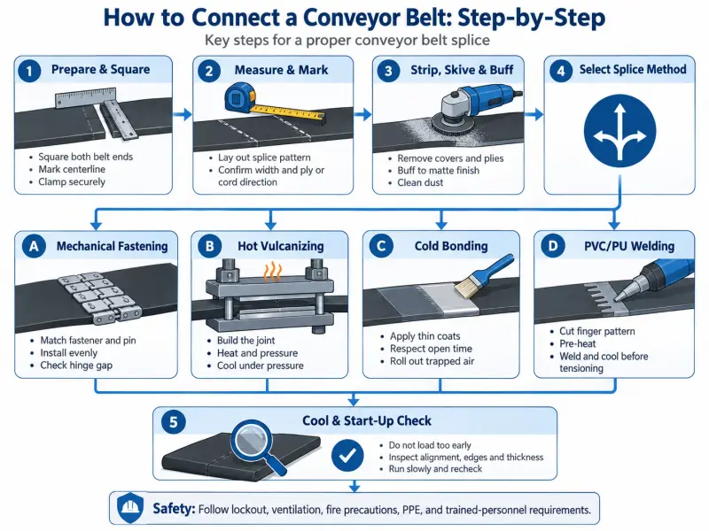
The sequence is the same whatever the method: square the ends, lay out the splice, prepare the surfaces, join, and control the cure. The steps below assume a trained crew working to the manufacturer’s splice specification.
9.1 Preparation and Squaring
Square both ends and check the diagonals so the joint is perpendicular to the belt centerline. Mark the centerline and secure the belt with clamps under an approved lockout procedure. Common error: squaring on a damaged or curved section, which builds a permanent tracking error into the joint.
9.2 Measuring and Marking the Splice
Take step lengths, finger lengths, and the cover bevel from the splice specification, and mark both ends so the patterns mirror each other. Confirm belt width and ply or cord direction before cutting. Common error: measuring from a damaged edge instead of the true centerline.
9.3 Stripping, Skiving and Buffing
Remove cover and plies to the marked depth without cutting into the ply below. Buff rubber to a matte finish, clean cords without nicking them, and remove all dust. Common errors are over-buffing, which thins the carcass and damages cords, and under-buffing, which leaves a glossy surface and a weak bond.
9.4 Mechanical Fastening Steps
Select the fastener and pin for the belt thickness, center the fastener, and drive the teeth or rivets fully. Leave the correct gap so the hinge can work, and confirm the pin passes by hand across the full width. Common error: an uneven gap that loads only a few teeth.
9.5 Hot Vulcanizing Steps
Build up the joint with tie gum and cover compound, align the ends in the press, and close it to apply pressure. Heat to the cure schedule, hold for the full time, and cool under pressure before releasing. Common error: opening the press while the joint is still hot.
9.6 Cold Bonding Steps
Apply the cement in thin coats with the specified open time, lay the plies in position, and roll from the center outward to remove air. Clamp the joint and leave it for the full cure time. Common error: touching the cemented surface, or shortening the cure to restart production.
9.7 PVC/PU Welding Steps
Cut the finger pattern, pre-heat the ends, and weld at the temperature and speed recommended for the belt and weld rod. Apply roller pressure behind the nozzle and let the seam cool before tensioning. Common error: welding too fast, which leaves the material below fusion temperature.
9.8 Cooling and First Start-Up Checks
Do not tension or load the belt until the joint has cooled. Check the joint for thickness steps, open edges, blisters, and alignment, then run the belt slowly and watch the joint pass the scrapers, skirt boards, and pulleys. Inspect again after the first few revolutions and after the first full shift.
Figure 5 – First start-up check at the joint, with the crew watching the joint pass the scraper and pulley. Image to be supplied by the manufacturer.
Splicing work involves cutting tools, solvents, hot air equipment, heaters, and presses. Work must follow the site safety rules, including lockout, fire precautions, ventilation, personal protective equipment, and trained personnel. Where the environment is classified as explosive, or the belt runs underground, the equipment and procedure must be approved for that use.
10. How to Build a Stepped Splice on an EP Fabric Belt
The sections above explain which joint to use. This one explains how a stepped splice is actually built on a fabric belt, such as EP or NN. The geometry, the lay-up order, and the cure control below follow DIN-based splice practice. The belt’s own splice specification always takes precedence over the example values.
Figure 6 – Marked step pattern on a three-ply EP belt end, with the diagonal splice line and the step lines. Image to be supplied by the manufacturer.
10.1 Step Count and Splice Length
The number of steps follows the ply count. A belt with N plies is normally built with N minus one steps, so a three-ply EP belt gets two steps and a five-ply belt gets four. The splice length is the step length multiplied by the number of steps. A single-ply belt is the exception: it is joined as a single lap, with the step length and the splice length equal.
The joint is cut on the diagonal for belts with two or more plies and bonding rubber. The diagonal is offset by about 0.3 times the belt width, and domestic after-sales practice often increases that to 0.5 times the width, which moves the joint line away from both belt edges. A right-angle joint is used only in special cases, such as a belt made from one piece.
Belt designation (N/mm total / plies) | Strength per ply (N/mm) | Minimum step l_st (mm) | Splice length l_v (mm) | Steps |
200/2, 250/2 | 100-125 | 250 | 250 | 1 |
315/2, 400/2 | 150-200 | 300 | 300 | 1 |
500/2 | 225-250 | 350 | 350 | 1 |
315/3 | 80-100 | 150 | 300 | 2 |
400/3, 500/3 | 125-160 | 200 | 400 | 2 |
630/4 | 125-160 | 200 | 600 | 3 |
800/4 | 200-250 | 250 | 750 | 3 |
1000/5, 1250/5 | 200-250 | 250 | 1000 | 4 |
1600/5, 2000/5 | 315-400 | 300 | 1200 | 4 |
2500/5, 3150/5 | 500-630 | 350 | 1400 | 4 |
These are reference values taken from a DIN-based endless belt splice specification, shown so the reader can see how the geometry scales with belt strength and ply count. They are not a substitute for the splice specification issued for the belt in front of you. For a designation outside this range, calculate the strength per ply first, find the matching minimum step length, and multiply it by the ply count minus one.
10.2 Marking the Belt Ends
Square both belt ends and draw the centerline on each. Set the step lines out from the centerline rather than from the belt edges, and mirror the pattern on the two ends so the steps interlock. Decide which end is the (a) end and which is the (b) end before any cutting begins, because one end is stripped from the top cover and the other from the bottom cover. On a patterned belt, the running direction decides which end has to become the (a) end.
10.3 Stripping and Grinding the Steps
Strip the covers and plies back to the marked lines one ply at a time, without cutting into the ply underneath. Grind the exposed steps with an electric wire wheel until the old rubber is gone, but never grind into the fabric itself. Bevel the cover and edge rubber where it meets the joint; the bevel length is about twice the rubber thickness at that point. Clean the whole area and let it dry before any cement is applied.
10.4 Cement and Lay-Up Order
Brush the cement onto the ground steps and the joint surfaces in two coats, letting the first coat dry before the second is applied. Once the cement is dry, lay the (a) end onto the tie gum and bring the (b) end into position. The steps are built in reverse order so that the original ply sequence is restored: each ply of one end meets its matching ply in the other, and the step edges are lapped across the belt by 8 to 10 mm rather than butted on a DIN splice. Align the two centerlines, then roll from the middle of the joint outward toward both edges so trapped air is pushed out.
10.5 Cover, Edge Rubber and Finishing
Rebuild the cover and edge with the joint rubber recommended for that belt, applied slightly thinner than the original cover so that rolling brings it back to belt thickness. Work the rubber down with a hand roller and a stitching awl so no air remains beneath the cover, and trim any compound squeezed out of the joint. Mark the running direction and a joint reference number on the top cover.
10.6 Cure Control
The joint is cured in a heated platen press. A DIN-based schedule uses a platen temperature of 145 C to 151 C and a unit pressure of 1.5 to 3.0 MPa, with the platen extending at least 100 mm beyond the splice length and 50 mm beyond the belt width on each side. Cure time is calculated from the construction rather than guessed. A common DIN formula is T = 14 + 0.7P + 1.6(A + B) minutes for joints under 25 mm thick, and T = 17 + 0.7P + 2(A + B) for thicker joints, where P is the ply count and A and B are the upper and lower cover thicknesses in millimetres.
Two timing rules matter as much as the temperature. The prepared ends should be assembled within 24 hours of grinding, and the joint should be cured within 48 hours. After the cure, switch off the heat and wait until the platen has fallen below about 70 C before opening the press, because releasing a joint while it is still hot allows the layers to separate.
10.7 Where These Numbers Must Come From
Every value in this section is a reference, not a specification. Step length, splice length, diagonal offset, cover bevel, joint compound, cure temperature, pressure, and cure time are issued for one specific belt construction, cover grade, and press. Take them from the splice specification that applies to the belt being joined, and treat this section as a check that the specification you have been given is complete.
11. Why Conveyor Belt Joints Fail
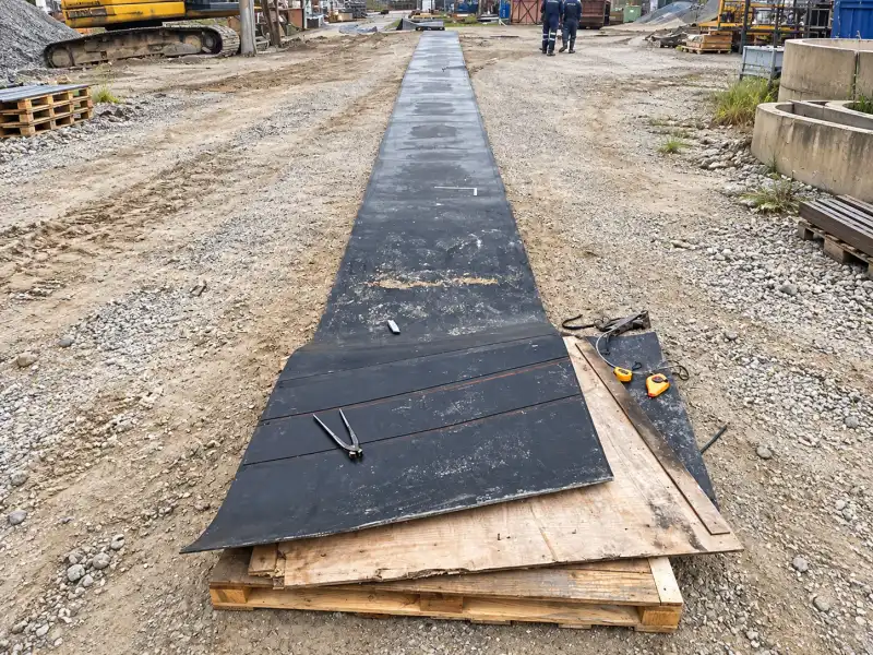
A joint fails for a reason, and the reason can usually be traced to one of five sources: a joint that does not suit the belt or the duty, incorrect geometry, contaminated or damaged surfaces, an incorrect cure or weld, or overloading and misalignment in service.
11.1 Step Edge Opening
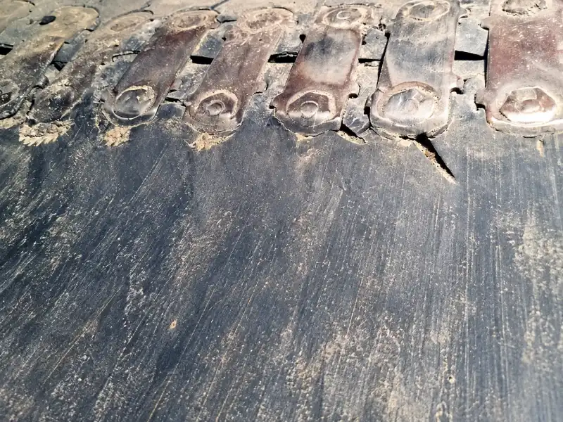
The step edge lifts and opens first because it is where the load transfers between plies. Frequent causes are insufficient buffing, insufficient pressure during the cure, trapped moisture or solvent, a step length below specification, and load above the joint’s design level. Damage from a scraper or skirt board beside the joint looks similar and is often mistaken for a bonding fault.
11.2 Blisters and Delamination
Blisters are voids, and voids come from air, moisture, or solvent trapped during build-up, or from pressure too low to close the layers. Delamination along a step can also follow over-buffing, contamination, or the wrong compound. When blisters appear on one side only, check the press for uneven heat or an untrue platen as well as the workmanship.
11.3 Fastener Pull-Out
Fasteners pull out when the holes enlarge under movement, when the belt is misaligned so the load is uneven, when the fastener is too light for the tension, or when the belt is too thin for the fastener’s bite. A joint that has been re-tensioned several times has usually already lost the section it needs to hold.
11.4 Mistracking at the Joint
A joint is a transverse discontinuity, so any error in it steers the belt. Ends that are not square, a thickness difference across the width, uneven tensioning during the cure, or a hinge pin that is not straight will all cause the belt to move sideways as the joint passes. Check the joint geometry before adjusting the conveyor.
11.5 Damage from Scrapers and Skirt Boards
Even a correctly made joint has a small step, and a scraper or skirt board set too close will catch it. The damage is often reported as a joint problem when the cause is the cleaning system. Set blade pressure and skirt clearance to suit the belt and the joint, and re-check them after the first run with a new splice.
11.6 Inspection Checklist
- Mark the position of every joint on the belt so it can be found during inspection.
- Inspect each joint at every planned belt inspection, not only when a fault is reported.
- Record the opening width, joint thickness, alignment, and exposed metal.
- Photograph the same locations at each inspection so small changes stay visible.
Symptom | Likely cause | How to check | Prevention |
Step edge opening | Short step, poor preparation, low pressure, or overload | Measure the opening; check step length against the specification | Build to the specified pattern; control pressure and cure |
Blisters or delamination | Trapped air or moisture, contamination, wrong compound | Inspect both faces; look for a pattern linked to one side of the press | Dry and clean the surfaces; apply correct pressure; verify the compound |
Fastener pull-out | Enlarged holes, misalignment, fastener too light for the tension | Count damaged fasteners and measure hole growth; check alignment | Use the correct fastener; correct tracking; limit re-tensioning |
Mistracking at the joint | Ends not square, uneven thickness, or an untrue pin | Check squareness, thickness across the width, and pin straightness | Square the ends; check thickness; replace a bent pin |
Scraper or skirt board damage | Blade pressure or clearance set too close | Inspect the joint as it passes the scraper and skirt | Set the cleaning system to suit the belt and joint; re-check after start-up |
12. Key Takeaways and Practical Guidance
Three things decide a conveyor belt joint: the carcass, the tension, and the duty. Fabric belts can be joined mechanically, cold bonded, or vulcanized. Steel cord belts need a multi-stage vulcanized splice, and PVC/PU belts need a welded finger splice. Match the method to the belt, follow the splice specification, and control preparation and cure. That is what separates a joint that runs for years from one that fails in weeks.
12.1 References and Further Reading
Standards and documents used as the technical basis of this article:
- GB/T 7984-2013, Conveyor belts of textile construction for general use , modified from ISO 14890:2003.
- GB/T 9770-2013, Steel cord conveyor belts for general use , based on ISO 15236-1:2005.
- GB/T 10822-2014, Flame retardant conveyor belts of textile construction for general use .
- GB/T 20021-2017, Heat resistant conveyor belts of duck construction .
- GB/T 33510-2017 / ISO 4195:2012, Conveyor belts with heat-resistant rubber covers: heat resistance of covers, requirements and test methods.
- HG/T 3973-2023, Flame retardant steel cord conveyor belts for general use .
- GB/T 3690-2017 / ISO 283:2015, Textile conveyor belts: full thickness tensile strength and elongation, test method.
- GB/T 6759-2013 / ISO 252:2007, Conveyor belts: adhesion between constitutive elements, test methods.
- GB/T 4490-2009 / ISO 251:2003, Textile conveyor belts: widths and lengths. Superseded by GB/T 4490-2021.
- GB/T 3685-2017 / ISO 340:2013, Conveyor belts: laboratory scale flammability characteristics, test method.
Standards commonly quoted for splice design, including DIN 22102 for textile carcass belts and DIN 22131 and ISO 15236 for steel cord belts, set belt construction and test requirements. The edition, the splice strength grade, and any acceptance criterion must be taken from the current version of the standard and from the belt manufacturer’s splice specification. A standard number alone is not a joint design.
This article also reflects general belt maintenance practice and the factory splice process specification held by the belt supplier. Manufacturer installation manuals for vulcanizing presses, welding equipment, and fastener systems, and the cure charts issued with belt and compound materials, take precedence over any general statement here.
13.Frequently Asked Questions
13.1 What is the difference between a conveyor belt joint and a splice?
In normal use they mean the same thing: the finished connection between two belt ends. Splice is the more common word in belt maintenance, especially for a vulcanized connection, and joint is used in standards and general descriptions. Neither word describes hardware; a fastener or clip is the part that connects the ends in one type of joint.
13.2 What are the main types of conveyor belt joints?
There are three families. Mechanical joints use metal fasteners driven into or clamped onto the belt. Cold bonded joints use cement systems that cure at ambient temperature. Hot vulcanized joints use uncured rubber cured under heat and pressure. Within the mechanical family, the main types are plate, hinged or butterfly, toothed, and wire hook fasteners.
13.3 Which conveyor belt joint is the strongest?
A correctly made hot vulcanized splice retains the most strength, and on a steel cord belt it is the only acceptable production joint. A cold bonded joint retains less, and a mechanical joint retains the least because it punctures the carcass. Preparation, geometry, and cure control decide whether any splice reaches its expected strength.
13.4 Can a steel cord conveyor belt be joined with mechanical fasteners?
No, not as a production joint. A mechanical fastener cannot reconnect the steel cords that carry the tension, and the teeth or rivets damage the cords and the rubber around them. Steel cord belts should be joined with a multi-stage vulcanized splice built to the manufacturer’s specification. A fastener may be considered only as a short-term measure, and only with the manufacturer’s agreement.
13.5 How long does a vulcanized conveyor belt joint last?
There is no universal figure. Service life depends on the belt, the splice design, the quality of the work, the load, the pulley and scraper conditions, and the environment. A joint should be judged by inspection and by trend, not by a fixed life. Watch the step edges, the thickness, and the alignment, and compare each inspection with the previous record.
13.6 How do you join a PVC conveyor belt?
PVC and PU belts are joined by welding. The ends are cut into interlocking fingers, heated until the material softens, and pressed together. A butt weld with filler keeps the belt thickness uniform, while an overlap weld is simpler but leaves a step. Very light PVC belts can also be joined with mechanical clips, or with high-frequency welding where the construction suits it.
13.7 Can you repair a conveyor belt joint on site?
Yes, in many cases. A cold bonded patch can close an opening or a small repair area, and a portable vulcanizing press can re-cure a joint on the belt line. A mechanical repair can restore production quickly. The limit is the carcass: if cords or plies are broken or contaminated, a patch will not restore the joint, and the belt length should be re-spliced.
13.8 How do you know when a conveyor belt joint needs to be replaced?
Replace or re-splice the joint when a step edge keeps opening after repair, when blisters or delamination spread, when fasteners pull out repeatedly at the same location, when joint thickness or alignment changes, or when the damage reaches the carcass. Small, stable defects can be monitored. Any defect that is growing, or that has exposed the load-bearing structure, needs planned replacement.